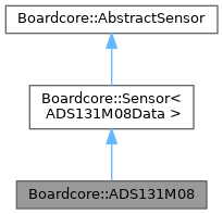
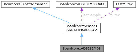
Driver for ADS131M08 8 simultaneous channels adc. More...
#include <ADS131M08.h>


Classes | |
| struct | Config |
Public Member Functions | |
| ADS131M08 (SPIBusInterface &bus, miosix::GpioPin cs, SPIBusConfig spiConfig, const Config &config) | |
| bool | init () override |
| Initialize the sensor. | |
| bool | reset () |
| void | applyConfig (Config config) |
| Overwrites the sensor settings. | |
| void | calibrateOffset (ADS131M08Defs::Channel channel) |
| Samples each channel, averages the samples and applies offset compensation in the device. | |
| bool | selfTest () override |
| The self test samples internally connects each channel to known test signals and verifies if the sampled values are in an expected range. | |
 Public Member Functions inherited from Boardcore::Sensor< ADS131M08Data > Public Member Functions inherited from Boardcore::Sensor< ADS131M08Data > | |
| Sensor () | |
| Sensor (Sensor &&other) | |
| virtual | ~Sensor () |
| void | sample () override |
| Sample the sensor. | |
| virtual ADS131M08Data | getLastSample () |
 Public Member Functions inherited from Boardcore::AbstractSensor Public Member Functions inherited from Boardcore::AbstractSensor | |
| virtual | ~AbstractSensor () |
| SensorErrors | getLastError () |
| Get last error for debugging purposes. Avoid silent fails. | |
Protected Member Functions | |
| ADS131M08Data | sampleImpl () override |
| Read a data sample from the sensor. In case of errors, the method should return the last available correct sample. | |
Additional Inherited Members | |
 Public Types inherited from Boardcore::Sensor< ADS131M08Data > Public Types inherited from Boardcore::Sensor< ADS131M08Data > | |
| using | DataType = ADS131M08Data |
 Protected Attributes inherited from Boardcore::Sensor< ADS131M08Data > Protected Attributes inherited from Boardcore::Sensor< ADS131M08Data > | |
| DataType | lastSample |
| miosix::FastMutex | mutex |
 Protected Attributes inherited from Boardcore::AbstractSensor Protected Attributes inherited from Boardcore::AbstractSensor | |
| SensorErrors | lastError = SensorErrors::NO_ERRORS |
Detailed Description
Driver for ADS131M08 8 simultaneous channels adc.
The ADS131M08 is an eight-channel, simultaneously-sampling, 24-bit, delta-sigma (ΔΣ), analog-to-digital converter (ADC). The individual ADC channels can be independently configured depending on the sensor input. A low-noise, programmable gain amplifier (PGA) provides gains ranging from 1 to 128 to amplify low-level signals.
Each channel on the ADS131M08 contains a digital decimation filter that demodulates the output of the ΔΣ modulators. Offset and gain calibration registers can be programmed to automatically adjust output samples for measured offset and gain errors.
The device features a "global-chop mode" to reduce offset error and offset drift inherent to the device due to mismatch in the internal circuitry to very low levels. When global-chop mode is enabled by setting the GC_EN bit in the GLOBAL_CHOP_CFG register, the device uses the conversion results from two consecutive internal conversions taken with opposite input polarity to cancel the device offset voltage.
Each channel has a dedicated input multiplexer that controls which signals are routed to the ADC channels:
- The analog input pins corresponding to the given channel
- AGND, which is helpfu for offset calibraton
- Positive DC test signal
- Negative DC test signal
Each channel also feature an integrated programmable gain amplifier (PGA) that provides gains of 1 to 128. Each channel has an independent PGA.
The device communicates via SPI, the maximum allowed frequency is 25MHz.
The ADC can work on 3 different power configurations depending on the clock frequency:
- High-resulution: 250-32KSPS
- Low-power: 125-16KSPS
- Very-low-power: 62.5-8KSPS You will probably have the ADC in high resolution mode.
Definition at line 75 of file ADS131M08.h.
Constructor & Destructor Documentation
◆ ADS131M08()
| Boardcore::ADS131M08::ADS131M08 | ( | SPIBusInterface & | bus, |
| miosix::GpioPin | cs, | ||
| SPIBusConfig | spiConfig, | ||
| const Config & | config | ||
| ) |
Definition at line 35 of file ADS131M08.cpp.
Member Function Documentation
◆ applyConfig()
| void Boardcore::ADS131M08::applyConfig | ( | Config | config | ) |
Overwrites the sensor settings.
Writes a certain config to the sensor registers. This method is automatically called in ADS131M08::init() using as parameter the configuration given in the constructor.
- Parameters
-
config The configuration to be applied.
Definition at line 76 of file ADS131M08.cpp.
◆ calibrateOffset()
| void Boardcore::ADS131M08::calibrateOffset | ( | ADS131M08Defs::Channel | channel | ) |
Samples each channel, averages the samples and applies offset compensation in the device.
Definition at line 91 of file ADS131M08.cpp.
◆ init()
|
overridevirtual |
Initialize the sensor.
- Returns
- boolean value indicating whether the operation succeded or not
Implements Boardcore::AbstractSensor.
Definition at line 43 of file ADS131M08.cpp.
◆ reset()
| bool Boardcore::ADS131M08::reset | ( | ) |
Definition at line 50 of file ADS131M08.cpp.
◆ sampleImpl()
|
overrideprotectedvirtual |
Read a data sample from the sensor. In case of errors, the method should return the last available correct sample.
- Returns
- sensor data sample
Implements Boardcore::Sensor< ADS131M08Data >.
Definition at line 293 of file ADS131M08.cpp.
◆ selfTest()
|
overridevirtual |
The self test samples internally connects each channel to known test signals and verifies if the sampled values are in an expected range.
- Returns
- True if the self test is successful, false otherwise.
Implements Boardcore::AbstractSensor.
Definition at line 151 of file ADS131M08.cpp.
The documentation for this class was generated from the following files:
- src/shared/sensors/ADS131M08/ADS131M08.h
- src/shared/sensors/ADS131M08/ADS131M08.cpp